Transformer
Subject: Science

Overview
A transformer is a device used to change the voltage of an alternating current. It is used in power plants, transmission, and distribution of energy. Transformers consist of two coils of thin, insulated copper wire, which create an electromagnetic field (emf) when an alternating current flows through them. The mutual induction principle is the foundation for transformers, which cannot modify the voltage of direct current. The core is constructed by tying several iron sheets coated with non-conductive paint to prevent excessive core heating. The number of turns in the transformer's coils determines whether the input voltage increases or decreases. The ratio of the primary voltage to the secondary voltage in a transformer is equal to the ratio of the turns in the primary coil to the secondary coil.
The mobile charger's specified output voltage rating of 5.3V is seen in the figure. We plugged up the mobile charger to a circuit that had a 220V alternating current (AC). In this case, the gadget within the charger lowers the 220 a.c. to 5.3 V a.c. needed to charge the phone.
In a microwave oven, the same 2100V is needed to produce microwaves. In order to do this, a transformer mounted within the oven changes 220V AC to 2100V AC. In this sense, a transformer is a device that is used to change the voltage of an alternating current.
Three main components make up the utilization of a.c. electricity: generation, transmission, and distribution. The powerhouse's generator transforms the electricity it produces into a high voltage (132 kV, for instance) a.c. before it is sent across the transmission line. At the load transmission center (substation), the voltage of the transmitted electricity is lowered to a lower value (for instance, 220V) prior to being distributed for consumption. Powerhouses and load transmission centers employ transformers to adjust the voltage as needed.
High-voltage transmission lines allow the nation's power plants to send their generated electricity both inside and beyond the nation. For instance, 400KV power is transmitted at the Dhunsha load transmission station.
Construction and Working Principles of Transformer
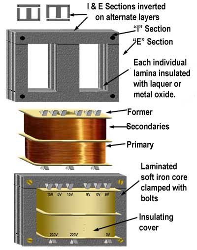
 The functioning concept of transformers used in power plants and transformers used for the transmission and distribution of energy is the same, despite certain structural variations between the two types of transformers. Two coils consisting of thin, insulated copper wire are included in them. Two coils make up a transformer, as seen in the figure, which is utilized in electrical equipment. It is not linked to these coils. When an alternating current flows through a coil, a magnetic field that is constantly changing surrounds it. Thus, an electromagnetic field (emf) is created in the coil when the magnetic strength associated with the neighboring coil varies. Next, the two ends of this coil are pulled to extract the output current. The mutual induction principle states that emf may be produced in a coil by altering the current in the coil next to it. The mutual induction concept serves as the foundation for the transformer. A transformer cannot be used to modify the voltage of direct current since there is no mutual induction when direct current flows in the coil instead of alternating current.
To keep the coils apart in a transformer, the core is constructed by tying several E, U, and shaped iron sheets coated with non-conductive paint into a single block with the help of nuts and bolts. We refer to this procedure as core lamination. By laminating the transformer's core, excessive core heating that results from a shift in the magnetic flux linkage's induced current may be avoided. The main coil of the transformer is the one that receives alternating current input (also known as the input coil), while the secondary coil induces alternating current output (also known as the output coil). Main turns (Np) are the number of turns of wire wound in the main coil; secondary turns (Ns) are the number of turns of wire twisted in the secondary coil. The main and secondary windings of the transformer are kept apart in order to adjust the voltage of the alternating current flowing through them. The transformer's input voltage, also known as the primary voltage (Vp), is the AC voltage applied to the primary coil, and the output voltage, also known as the secondary voltage (Vs), is the AC voltage received from the secondary coil.
Types of Transformer
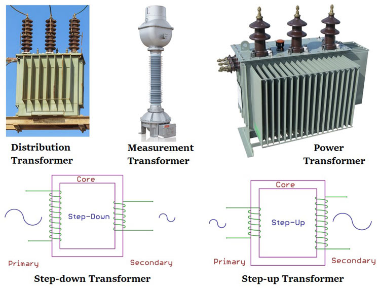
The number of turns in the transformer's coils determines how much the input voltage is increased or decreased. In the transformer block diagram seen in the figure, the proportion of primary windings to secondary windings is 2:1. The output voltage of the aforementioned transformer is precisely half of the input value, or 110V, if the input voltage is 220V. When the secondary coil of a transformer has fewer turns than the main coil, the voltage decreases. A step-down transformer is a transformer that lowers the voltage of an alternating current.
In the transformer block design seen in the figure, the proportion of primary windings to secondary windings is 1:2. The output voltage of the aforementioned transformer is precisely double the input value, or 220V, if the input voltage is 110V. The voltage is increased in a transformer when the secondary coil has more windings than the main coil has. A step-up transformer is a transformer that raises the voltage of an alternating current.
The ratio of the primary voltage to the secondary voltage in a transformer is equal to the ratio of the turns in the primary coil to the turns in the secondary coil. This may be expressed as the formula for the transformer:
\(\frac{Primary\:turns\:(N_{p})}{Secondary\:turns\:(N_{s})}= \frac{Primary\:Voltage\:(V_{p})}{Secondary\:Voltage\:(V_{s})}\)
Example
Let's work through a simple example to illustrate the use of this formula:
Suppose you have a transformer with the following values:
- Primary turns (\(N_p\)): 200 turns
- Secondary turns (\(N_s\)): 100 turns
- Primary voltage (\(V_p\)): 240 volts
Now, you can use the formula to find the secondary voltage (\(V_s\)): \[\frac{N_p}{N_s} = \frac{V_p}{V_s}
\]
Substitute the given values: \[\frac{200}{100} = \frac{240}{V_s}
\]
Now, solve for \(V_s\): \[\frac{2}{1} = \frac{240}{V_s}
\]
Cross-multiply: \[2 \cdot V_s = 240 \cdot 1
\]
Simplify: \[2V_s = 240
\]
Divide by 2 to solve for \(V_s\): \[V_s = \frac{240}{2} = 120 \text{ volts}
\]
So, in this example, the secondary voltage (\(V_s\)) is 120 volts. This demonstrates how you can use the transformer formula to relate the number of turns and voltages in the primary and secondary coils of a transformer.
Things to remember
- Transformers are devices used to change the voltage of an alternating current, which are used in power plants and the transmission and distribution of energy.
- When an alternating current flows through a coil, a magnetic field surrounds it, creating an electromagnetic field (emf).
- The number of turns in the transformer's coils determines how much the input voltage is increased or decreased.
- A step-down transformer is a transformer that lowers the voltage of an alternating current.
- A step-up transformer is a transformer that raises the voltage of an alternating current.
- The ratio of the primary voltage to the secondary voltage in a transformer is equal to the ratio of the turns in the primary coil to the turns in the secondary coil.
© 2021 Saralmind. All Rights Reserved.


 Login with google